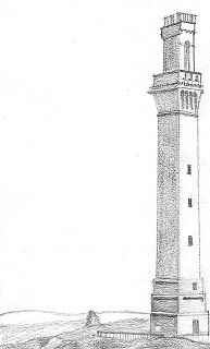
Drawing is a monochrome sketch of a selected subject made with a writing instrument using the principles of perspective and light for the purpose of evoking contemplation. Drawing consists of the selective indication of a few attributes from the collection of all attributes that make up the subject. For instance, notice the use of perspective for 3D effect and the use of shading to indicate shadows. Additionally, the selection of the vantage point that starkly contrasts the horizontal landscape on the left with the vertical rise of the monument makes the tower the focus of attention.
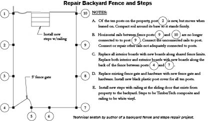
Engineering drawing, on the other hand, is a monochrome sketch of a design for a utilitarian object made with a writing instrument using the principles of orthographic projection and methods of construction for the purpose of implementing, operating, or maintaining a design. Engineering drawing consists of the complete indication of all components and their arrangement for the design that is supplemented with construction specifications and methods. For instance, the line work for the fence repair project below is a schematic plan view that is supplemented with symbols, the bubble call-outs for instance, and notes specifying attributes and construction methods.
Whereas an artist’s drawing can be understood by anyone; an engineering drawing requires an understanding of the design’s engineering discipline it represents. The elements of an Engineering Drawing can be broadly indicated with the following essential components of the Language of Engineering Drawing:
- Geometric Representation (Overview, Index, Arrangement of Implementation by Discipline)
- Specification for Implementation (Definition, Material, Method)
- Resource Requirements (Description, Unit of Measure, Quantity)
Every engineering student must know how to represent his design in the language of engineering drawing. Even one not in the business of creating designs, but in the business of implementing, operating, or maintaining them must be able to read and interpret engineering drawings and be able to assess their accuracy and completeness.

Because the line work in engineering must be accurate, one does not construct engineering drawing freehand but instead uses geometric instruments. When engineering drawing is made freehand, it is called technical sketching.
A technical sketch is an engineer's tool to quickly represent the design intent that, should there be a need, can be transcribed into an accurate engineering drawing by a trained draftsman in the same trade as the engineer.
The purpose of this book is to help you discover the Language of Engineering Drawing by teaching yourself the content (technical sketching, engineering drawing, modeling, virtual-reality) and method (Drafting, CAD, EaaS) of engineering drawing.
The Geometric Representation of an engineering drawing is graphical, supplemented with symbols, and are not meant to be spoken literally but interpreted in the context of the engineering discipline. The Specification for Implementation, and Resource Requirements, use the tool of communication, i.e. language, to convey methods and quantities.
As we embark on the study of Drafting, CAD, and EaaS, it is vital that we first take the time to understand the media (paper, electronic model, electronic reality) in which can exist the content of engineering drawing.
